CCIE Pursuit Blog

August 17, 2009

Internetwork Expert Volume IV (Troubleshooting) Workbook Review: Part 3

Once you get the initial configurations loaded you’re ready to begin the lab.  This is when the “fun” begins.  Those of us who are used to starting labs with barebone configurations and searching for a few misconfigurations will be in for a bit of a shock.  This is not how this troubleshooting will go.  You’ll be looking at a fully configured network…which you did not build. It was at this point that I should have realized that this would not be easy and that the 2 hour time limit – which initially sounded like all of the time in the world – would be an issue.

When I tell you that you’re looking at a fully configured network, that means things like QoS, Multicast, and IP Services.  You can start to see how difficult Cisco can make these labs.  Throw in a number of devices that you cannot access and INE’s recommendation that you only use show and debug commands, and you’re looking at a bad day on the CLI.

The lab document starts with a “Baseline” section.  This will give you a list of the devices under your control as well as details about how the network has been configured.  This is broken down by well-known sections.  For instance, Bridging and Switching might tell you which devices are STP roots, which VLANs are present, which flavor of STP is running, if and how VTP is set up, etc.  The IGP section describes the routing protocols, any route filtering, redistribution (yes, there is plenty of that), etc.

I read through the baseline and then started making network maps.  INE has some nice examples of the maps that you’ll want to build and how long it should take in the solution guide:

We recommend making your own diagrams, including the following
information:
• IP addressing + IGPs.
• Layer 2 topology.
• BGP diagram.
• IPv6 topology.
• Multicast and Redistribution diagram.

Overall, don’t spend too much time building the baseline – the goal is to spend around 20 minutes. By the end of the baseline analysis phase, you should have clear understanding of the protocols and applications deployed in your network.

It took me a LOT longer than 20 minutes to get my head around what was going on in the network.  It’s much harder to get quickly up to speed on a complex CCIE network when you haven’t built it from scratch.  😦

After getting a basic idea of what was going on, it was time to start looking at the tickets.  There are ten tickets, each with a point value between 2 to 4 points.  The total amount of points is 30 points, so each ticket will average 3 points.  Like the “classic lab”, you’ll need to fix each issue completely – no partial points are awarded.  There may also be tickets that you cannot resolve unless you’ve already fixed previous tickets.  For example, ticket 10 in lab 1 has the following requirements:

Ticket 10: Multicast
Note: Prior to starting with this ticket make sure you resolved Tickets 4 and 5

Since you need 80% to pass the troubleshooting portion of the lab, you’ll need to get at least 24 points.  This means that you can only really miss about 2 tickets (depending on point values).

Logging is turned off on the devices.  I would strongly suggest enabling logging buffered on all devices(remove the configuration before finishing the lab).  There are a number of logging messages that will point to some initial issues that you might miss if you’re not on the device when the log is generated.  This way you can issue “show log” and see what’s going on.

Another suggestion: work on the tickets that seem easy first.  Then work on any tickets that are requirements for other tickets.  Finally, work on the tougher tickets last.

I used some of my basic, initial troubleshooting habits to find a couple of issues.  In the lab – after building each section – I do basic troubleshooting.  For instance, once all Layer 2 configuration is complete, I verify that I can ping across each link.  After each IGP configuration, I verify that the proper routes are being advertised and received, as well as pinging (at least a subset) of the routes.  I would suggest putting together a “toolkit” of common commands to run on each device when approaching the troubleshooting section such as ‘show ip int br | e ass’, ‘show ip protocol’, ‘show ip [protocol] route’, etc.

Let’s look one of the (easy) tickets from Lab 1:

Ticket 4: Connectivity Issue
• Another ticket from VLAN7 users. They cannot reach any resource on VLAN 5 – all IP Phones have unregistered, and nothing else works.
• However, they are still able to reach the local resources.
• Using the baseline description as your reference, resolve this issue in optimal manner.

3 Points

You will notice this issue if you do a Layer 2 check by pinging across directly connected links.  Basically, you cannot ping from r4 to sw1 on VLAN41.  Looking at sw1, I could see that the SVI interface for VLAN41 was not up.  Sounds like an easy fix.  Make sure that VLAN 41 has been added to the VLAN database.

Actually, it VLAN41 was in the VLAN database.  The IP addressing was correct.  All of the other SVIs were up and working.  WTF?

Here is the configuration for the SVI:

interface Vlan41
ip address 164.16.47.7 255.255.255.0
ip access-group REMOTE_DESKTOP in
ip pim sparse-dense-mode
ntp broadcast client
ntp broadcast

Hmmm….I’ll bet that INE has a dastardly access-list configured.  Let’s see the configuration for that sucker:

ip access-list extended REMOTE_DESKTOP
dynamic RDP timeout 10 permit tcp any host 164.16.7.100 eq 3389
deny   tcp any host 164.16.7.100 eq 3389
permit ip any any

Oh fucking joy.  A dynamic access-list.  But I don’t see how this would be breaking connectivity, let alone keeping my SVI down.  Just to be sure I removed the ACL.  The SVI remained down, but I did catch a break when issued ‘no shut’ after readding the ACL:

*Mar  1 02:19:56.300: %SPANTREE-2-ROOTGUARD_BLOCK: Root guard blocking port FastEthernet0/14 on VLAN0041.

Interesting.  According to our baseline guidelines sw1 should be the root bridge for all active VLANs.  The initial configuration reflects this:

spanning-tree vlan 1-4094 priority 8192

Fa0/14 is a trunk link to sw2:

interface FastEthernet0/14
switchport trunk encapsulation dot1q
switchport mode trunk
spanning-tree guard root

So it looks like someone is generating a better BPDU for VLAN41.  Wanna bet that it’s either sw3 or sw4 – the two switches that are restricted?  🙂

Rack16SW2#sh spanning-tree root

Root    Hello Max Fwd
Vlan                   Root ID          Cost    Time  Age Dly  Root Port
—————- ——————– ——— —– — —  ————
VLAN0001          8193 0017.0e3f.3900        19    2   20  15  Fa0/14
VLAN0003          8195 0017.0e3f.3900        19    2   20  15  Fa0/14
VLAN0005          8197 0017.0e3f.3900        19    2   20  15  Fa0/14
VLAN0007          8199 0017.0e3f.3900        19    2   20  15  Fa0/14
VLAN0009          8201 0017.0e3f.3900        19    2   20  15  Fa0/14
VLAN0013          8205 0017.0e3f.3900        19    2   20  15  Fa0/14
VLAN0018          8210 0017.0e3f.3900        19    2   20  15  Fa0/14
VLAN0026          8218 0017.0e3f.3900        19    2   20  15  Fa0/14
VLAN0041          4137 0012.4337.1880        19    2   20  15  Fa0/17         <-NOTE!
VLAN0043          8235 0017.0e3f.3900        19    2   20  15  Fa0/14
VLAN0055          8247 0017.0e3f.3900        19    2   20  15  Fa0/14
VLAN0062          8254 0017.0e3f.3900        19    2   20  15  Fa0/14

Rack16SW2#sh spanning-tree vlan 41
VLAN0041
Spanning tree enabled protocol ieee
Root ID    Priority    4137                <-less than 8233 on sw1
Address     0012.4337.1880
Cost        19
Port        19 (FastEthernet0/17)
Hello Time   2 sec  Max Age 20 sec  Forward Delay 15 sec

Bridge ID  Priority    32809  (priority 32768 sys-id-ext 41)
Address     001f.9e4a.fa00
Hello Time   2 sec  Max Age 20 sec  Forward Delay 15 sec
Aging Time 300

Interface        Role Sts Cost      Prio.Nbr Type
—————- —- — ——— ——– ——————————–
Fa0/4            Desg FWD 19        128.6    P2p
Fa0/14           Desg FWD 19        128.16   P2p
Fa0/17           Root FWD 19        128.19   P2p             <-goes to sw3 not sw1!

I think that I’ve found my problem.  sw3 is advertising a lower priority for VLAN 41.  I went ahead and set the STP priority to 0 for ALL VLANs.  INE chose to only change VLAN 41.

Me:
Rack16SW1(config)#spanning-tree vlan 1-4094 priority 0

INE:
spanning-tree vlan 41 priority 0

Either way, this unblocked f0/14 for VLAN41 and restored the STP instance on that VLAN, which brought up the SVI…which brought up IP connectivity.  🙂

*Mar  1 02:33:29.608: %SPANTREE-2-ROOTGUARD_UNBLOCK: Root guard unblocking port FastEthernet0/14 on VLAN0041.

That should give you an idea of one of the easier tickets.  Even though this was a fairly easy issue, it threw me off my game because 99.99% of the time when I see an SVI down, it’s because the VLAN is not in the VLAN database.

In the final part of the review I’ll discuss the solution guide as well as my overall impressions.
August 10, 2009

Internetwork Expert Volume IV (Troubleshooting) Workbook Review: Part 2

Access to the Volume IV workbook is the same as for all INE workbooks.  Once you’re logged in you’ll find (at present) three troubleshooting labs available.  The workbook will eventually contain 10 troubleshooting scenarios.  Each lab contains 10 trouble tickets which vary in value from 2 – 4 points.  You’ll also get the lab topology, along with initial configurations and the solution guide.

INE Workbook IV

INE Workbook IV

I rented some rack time at INE’s rack rental company, Graded Labs.  I booked a single, 5.5 hour session and planned to attempt the first two labs.  You’re allotted 2 hours for each lab, so I figured I should be able to complete both labs.  I was very wrong.

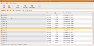
Graded Labs has a number of configurations for the INE product line which you can choose to have automatically loaded to your rack.  Unfortunately Graded Labs does not have the configs for the new Volume IV workbook yet.  This means that you will initially need to connect to each device and load in the appropriate config.  I had rented rack 16 and was worried that I would need to parse the initial configurations replacing IP addresses to fit the rack number, but INE has the initial configs for 31 different racks (1-30 and the mysterious rack 42) so you don’t need to go through the configs and change the IP addresses to match the rack.  It was just a matter of cutting and pasting in the appropriate configurations.

Initial Configurations For 31 Racks Included

Initial Configurations For 31 Racks Included

After loading the configurations, it was time to take a look at the lab.  I would very strongly recommend that you take the time to read the Workbook Introduction.  This six page PDF explains INE’s methodological approach to troubleshooting.  You will want to be familiar with it before attempting the labs as it will help you with troubleshooting as well as prepare you for the explanations in the solution guide.

After digesting the Workbook Introduction, it was time to look at the lab.  This is where the first surprises appear.

Lab Do’s and Don’ts:
•  Do not access the routers that are marked as restricted for your access.
•  Do not use the show running-config or show startup-config commands or their equivalents when performing troubleshooting.
•  Do not change or add any IP addresses from the initial configuration unless required for troubleshooting.
•  Do not change any interface encapsulations unless required for troubleshooting.
•  Do not change the console, AUX, and VTY passwords or access methods unless otherwise specified.
•  Do not use any static routes, default routes, default networks, or policy routing unless otherwise specified.
• Save your configurations often.

Those first two restrictions are killers.  While you will use the tried and true INE lab topology for these labs, each lab will include a number of restricted devices – outside of the normally restricted backbone devices.

The topology used for every scenario is the same that we use for all our RS products, including VOL1 (technology- focused labs), VOL2 (configuration mock lab scenarios) and VOL3 (core technologies scenarios).

However, unlike our previous workbooks, we restrict access to some of the devices in the lab topology. For every scenario this “restricted” set may be different and it is clearly outlined in the scenario’s baseline. Using this technique we increase the scenario complexity by allowing candidates to see only “one” side of the problem. When looking at the lab diagram, you will clearly see routers not under your control as being displayed in orange color. Also, when you log onto the “restricted” device, it will warn you using a banner message.

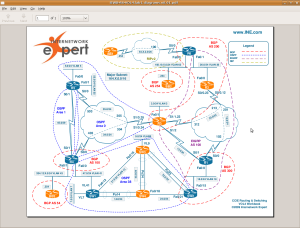
Lab 1 Topology - Note Restricted Devices in Orange

Lab 1 Topology - Note Restricted Devices in Orange

In lab 1 for instance, you are not allowed to access BB1, BB2, BB3, R2, R3, SW3, and SW4.  You’re pretty much on the honor system for the internal network devices as the you’ll be warned by a banner message, but only the first time you connnect (or if you telnet to the device(s)).

For instance, r3 is a restricted device:

Rack16R1#telnet 164.16.35.3
Trying 164.16.35.3 … Open

User Access Verification

Username: cisco
Password:

*****************************WARNING******************************
*                                                                *
*           Per the requirements of this scenario                *
*         You are not allowed to access this router              *
*                                                                *
*****************************WARNING******************************

Rack16R3>

You will not see the exec banner as long as the session to the console line is open from from the access server.  Regardless, it is important that you do not access the verboten devices during the lab.

While the restricted devices threw me an unexpected curve, it was the second requirement that really floored me.

In addition to the above restriction, we highly encourage you not using the show running-configuration, show startup-configuration commands or any other command that shows you the textual representation of the router’s configuration. This requirement makes you focus on using the show and debugging commands, which is invaluable when troubleshooting the real-world scenarios.

Our ultimate goal is not only prepare you for passing the Troubleshooting section of the CCIE R&S lab exam, but also to teach you a structured troubleshooting approach. As opposed to simple guessing and peeking at the routers running configurations you should learn using the debugging commands and interpreting various show commands output.

INE is serious about this too.  The solution guides will only use show and debugging commands to determine the root cause of each issue.  I don’t know if this will be a requirement in the actual lab; I certainly hope not!  In “real life” though, the use of debug commands is pretty much forbidden in the environments that I’ve worked in.  There’s a saying at my job “If you turn on a debugging command you had better have created a network change ticket, otherwise you’ve just created a job change ticket.”  Still, using the debug commands is a very good way to understand the underlying technology and there are some instances where you will get important troubleshooting information for a debug command that you cannot get in a show command.

For every ticket, we are going to follow the same structured procedure to resolve the issue.

Here is an outline of this procedure:

1. Build and Analyze the Baseline
2. Analyze the Symptoms (propose hypothesis)
3. Isolate the issue (gather more symptoms)
4. Fix the Issue (by comparing to the Baseline)

We recommend making your own diagrams, including the following
information:
• IP addressing + IGPs.
• Layer 2 topology.
• BGP diagram.
• IPv6 topology.
• Multicast and Redistribution diagram.

Overall, don’t spend too much time building the baseline – the goal is to spend around 20 minutes. By the end of the baseline analysis phase, you should have clear understanding of the protocols and applications deployed in your network.

This is a brief review of the systematic troubleshooting procedure that you’ll be using for the labs.  You’ll be familiar with the topology drawing bit from your practices labs.  Although, I did pick up some good tips from the solution guide about making topology maps.

Okay, enough jibba jabba about the labs.  Let’s actually dive into one.  That will be the focus of the next part of the review.

February 3, 2009

GroupStudy: Great CCIE Study Strategy

This recent posting to the GroupStudy mailing list contains a lot of great suggestions for CCIE candidates who are crafting/refining their study strategy:

1st) Do practice labs! It’s that easy, do as many as you can from a reputable vendor. I’m not here to prop one vendor over another…just find 1 (more if possible) that has a proven track record and do their labs. *The key is not so much the material but how you study it! Do the labs just like you’re are going to do the real lab! Meaning…in the real lab you don’t get to see the questions or the topology before hand, you don’t get to go to a proctor guide or google when you get stuck, you have 8 hours. So, when you have a lab manual, schedule your 8 to 10 hours, don’t look at any of the material before hand…then just sit there for 8 hours straight, beating your head against the wall, using only the doc cd. When you start, don’t touch a router until you have read through the whole lab, written down your “blue print” and point values and have a plan for the lab. Then go at it, if you get stuck or stumped, don’t look up the answer! Track your points and save your configs (maybe a show ip route or ip bgp or what ever is relevant as well) to your PC for grading yourself later.

When you have finished (either right after if you’re that impatient) or the next day go through the lab and grade it, be honest with yourself, and find out what you missed, then study it, learn it and understand it. (Those are your “off” days). Then, schedule your next Lab session and do it again!

At first you’ll get owned, feel like crap and wonder what in the hell you are doing. Probably will take you more than 10 hours to get through the labs, but do it all. After the first 5 to 10 you’ll get to where you can finish them in 8 hours, hopefully even sooner after 15 or 20 (the assumption is the labs get progressively harder but you are getting even faster). *part of completing a lab, is going back through the questions and verifying each task…without fail you will find at least one thing you did wrong or missed…that means you need to calculate that into your 8 hours. Get in the habit though

2nd) Once you have done 5 or 10 labs, if you are in a position, do a graded mock lab or… 7. See how you do. I wouldn’t worry so much about the score or “explanations” after the fact, but more of “did I come up with A solution for every section?” “Did I finish it in time?” “How was my time management?” “How well did I think on my feet?” (While I did not pass one of my mock labs, I always completed them, came up with solutions and learned how important it is to notice the little details) Use the mock labs to evaluate your testing strategy.

In all I did over 30 full labs (including my mock labs)…so sitting down for 8 hours in the real lab was nothing for me, I had been doing it 2 to 3 times a week for months. That kind of experience is crucial for success in the real lab. What’s more, I finish my lab (had a solution in place for each question) in 5 and a half hours and was able to spend the next 2 hours going back over each question. I easily earned between 15 to 25 points that way. Having that extra time allowed me to re-read scenarios, pick up on key-words, verify syntax et…You need to be able to get through the lab quickly…if you have done 20+ “labs” all ready, the real lab isn’t nearly as daunting in terms of time or manageability.

The point is this, you can’t do practice labs one way and think that you’ll do the real lab another. The real lab should be 2nd nature in terms of your initial read through and assessment, your time management and troubleshooting of individual scenarios, and your re-read and verification at the end.

I hope this has been helpful. Doing simple math 8 hours X 2 or 3 times a week = a lot of time and that doesn’t include the “off” days where you need to “grade” your self, study weak areas, practice configs, and browse the doc cd. It’s a huge investment of time, but if you’re going to do it, do it right and don’t “cheat” yourself.

December 9, 2008

Internetwork Expert: Volume II v5 Labs To Start Releasing This Week

Internetwork Expert’s December newsletter announces that their flagship workbook product is going to be updated:

Updated Routing & Switching Volume II Labs Start Releasing This Week

The newest updates to the Routing & Switching Volume II labs are being released in electronic format starting this week. The updates will automatically show up in your members site account as the labs are released.

The IE blog has a post up today with more detail:

This Friday the CCIE R&S Lab Meet-Up series kicks off with the new CCIE R&S Lab Workbook Volume 2 Version 5 Lab 1.  The new lab will be posted on the members site on Thursday, and the lab meet-up starts at 9am Pacific time.  The session should lab about 4 hours, depending on how many questions people have.  Essentially I will be configuring and explaining the lab live on the command line, and going through the logic of the solutions in detail.

It’s not too late to sign-up for the series, so contact our sales department if you have any questions.  I hope to see you there!

It looks like IE will be releasing the new labs one lab at a time with a Lab Meet-Up scheduled for each lab to discuss the lab/solutions.

October 30, 2008

Internetwork Expert: Details Of Today’s Announcement

Internetwork Expert CCIE 2.0 Upgrade

Internetwork Expert CCIE 2.0 Upgrade

UPDATE: That was quick.  IE has a blog posting about the new changes here.  You can view the recording of the announcement here.

—-

Internetwork’s vSeminar announcement today was so popular (over 500 people) that they had to turn away users as it filled up pretty quickly.  For those who missed it, there will be a recording on the IE site in the near future.  I’ll post some more details tomorrow, but here’s the quick and dirty:

Internetwork Expert will NOT be participating in the new 360 CCIE training programming.  They will be rolling out a new “CCIE 2.0” training program.  This program will involve a MUCH higher level of personalization.  This will included dynamic labs that will adapt to your strengths and test you more on your weaknesses.  There will be “Customer Success Managers” to help your chart and stay on your CCIE training path.  There will be the ability to purchase material “ala carte” to supplement your needs, rather than buying a one-size-fits-all end-to-end package.  There will also be constant assessment labs/tests to monitor your progress and make recommendations.  There will be more than $10,000 of worth of free training/credits available to community users (bloggers/forum users) who assist with answering training/technology questions.  IE will also begin hosting blogs on IEOC.  Existing customers will have their subscriptions upgraded.  IE will also be venturing into the CCNx (starting with CCENT in Q1 of 2009) training arena.  Next week there will be one or two more vSeminars that will go more into detail about the changes to CCIE 2.0

I’ll admit that this is a pretty exciting upgrade to IE’s existing CCIE training.  It will be interesting to see how well/quickly they can roll out this new model.  The good part is that they have been working towards this for at least nine months and it sounds like they have ramped up their payroll to be able to allocate resources towards this end.

August 17, 2008

Internetwork Expert Volume II: Lab 8 – Section 9

Section 9 – IP Services – 8 Points

9.1 Default Gateways

Users in VLAN 26 have their default-gateway set to their own IP address instead of r6’s address.  Configure r2 and r6 to support them.

WTF?  No clue.

The answer: turn off proxy-arp on those segments.

UPDATE:

It turns out that I read the question wrong. The requirement is:

“Configure r2 and r6 not [sic] support these users.”

It make sense to disable proxy-arp so as NOT to support these users.  The users are set up to ARP for everything.  Proxy-ARP is enabled by default so r2 and r6 will respond to ARPs with their own MAC address if they have a route for the address that the users ARP for. By disabling proxy-arp, the routers will not respond to those ARP requests.

9.2 Web Caching

Configure WCCP for users in VLAN 4.  The web servers are out the Frame link.

“Configure r4 to support this setup, but don not attempt to cache HTTP traffic between VLANs 4 and 45.”

How to Configure WCCP

r4(config)#int fa0/0
r4(config-if)#ip wccp web-cache redirect in
r4(config-if)#int s0/0
r4(config-if)#ip wccp web-cache redirect out

r4(config)#ip wccp ?
  <0-254>             Dynamically defined service identifier number
  check               Enable a WCCP check
  outbound-acl-check  Enable acl check on original outbound interface
  version             protocol version
  web-cache           Standard web caching service

r4(config)#ip wccp web-cache ?
  group-address  Set the multicast group
  group-list     Set the access-list used to permit group membership

  password       Authentication password (key)
  redirect-list  Set the access-list used to permit redirection
  <cr>

The three options that stand out as possibly being useful for the last requirement are the outbound-acl-check, the group-list, and the redirect-list.

I peeked the solution guide. 

Huh?

IE just enabled WCCP globally and then set s0/0 to redirect out???  Does that last requirement mean ALL HTTP request on VLANs 4 and 45 or just the traffic between those two VLANs (as I understood it)?

I get it now.  There are only two egress point for traffic from VLAN 4 or 45.  They can either egress the other VLAN or out the Frame link.  So IE’s solution makes sense.

9.3 IP SLA

This is a basic IP SLA task in which you must set up IP SLA on r6 to ping 115.0.0.1 every 30 seconds with 1250 byte packets and a timeout of 25ms.

I kept getting failures:

r6#sh ip sla mo stat
Round trip time (RTT)   Index 1
        Latest RTT: NoConnection/Busy/Timeout
Latest operation start time: *05:04:09.895 UTC Mon Mar 18 2002
Latest operation return code: Timeout
Number of successes: 0
Number of failures: 4
 
Operation time to live: 3503 sec

The reason was simple.  My packets were not fast enough.  🙂

r6#p 115.0.0.1 si 1250

Type escape sequence to abort.
Sending 5, 1250-byte ICMP Echos to 115.0.0.1, timeout is 2 seconds:
!!!!!
Success rate is 100 percent (5/5), round-trip min/avg/max = 28/28/32 ms

9.4 Gateway Redundancy

You need to use the SLA monitor in the last task with HSRP.  R6 should be VLAN 26’s default gateway but only if the SLA monitor is successful, otherwise they should use r2.

r6(config)#track 1 rtr 1

r6(config-track)#int f0/1.26
r6(config-subif)#stand 1 track 1decre 20
r6(config-subif)#stand 1 ip 174.1.26.1
r6(config-subif)#stand 1 preempt

r2(config)#int g0/0.26
r2(config-subif)#stand 1 ip 174.1.26.1
r2(config-subif)#stand 1 preempt
r2(config-subif)#stand 1 prio 90

Since my SLA monitor is failing, r2 should be active and r6 should have a priority of 80:

r2#sh stand
GigabitEthernet0/0.26 – Group 1
  State is Active
    1 state change, last state change 00:01:12
  Virtual IP address is 174.1.26.1
  Active virtual MAC address is 0000.0c07.ac01
    Local virtual MAC address is 0000.0c07.ac01 (v1 default)
  Hello time 3 sec, hold time 10 sec
    Next hello sent in 2.556 secs
  Preemption enabled
  Active router is local
  Standby router is 174.1.26.6, priority 80 (expires in 7.556 sec)
  Priority 90 (configured 90)
  IP redundancy name is “hsrp-Gi0/0.26-1” (default)

r6#sh stand
FastEthernet0/1.26 – Group 1
  State is Standby
    4 state changes, last state change 00:01:22
  Virtual IP address is 174.1.26.1
  Active virtual MAC address is 0000.0c07.ac01
    Local virtual MAC address is 0000.0c07.ac01 (v1 default)
  Hello time 3 sec, hold time 10 sec
    Next hello sent in 1.232 secs
  Preemption enabled
  Active router is 174.1.26.2, priority 90 (expires in 7.232 sec)
  Standby router is local
  Priority 80 (default 100)
    Track object 1 state Down decrement 20
  IP redundancy name is “hsrp-Fa0/1.26-1” (default)

Just to see if it will come up I deleted the SLA monitor and re-added it with a timeout and threshold of 50ms:

no ip sla monitor 1
ip sla monitor 1
type echo protocol ipIcmpEcho 115.0.0.1
request-data-size 1250
timeout 50
threshold 50
freq 5

ip sla monitor schedule 1 start-time now

r6#sh ip sla monitor stat
Round trip time (RTT)   Index 1
        Latest RTT: 28 ms
Latest operation start time: *05:14:18.275 UTC Mon Mar 18 2002
Latest operation return code: OK
Number of successes: 12 
Number of failures: 0

Operation time to live: 3543 sec

r6#sh stand
FastEthernet0/1.26 – Group 1
  State is Active
    8 state changes, last state change 00:01:09
  Virtual IP address is 174.1.26.1
  Active virtual MAC address is 0000.0c07.ac01
    Local virtual MAC address is 0000.0c07.ac01 (v1 default)
  Hello time 3 sec, hold time 10 sec
    Next hello sent in 2.296 secs
  Preemption enabled
  Active router is local
  Standby router is 174.1.26.2, priority 90 (expires in 7.296 sec)
  Priority 100 (default 100)
    Track object 1 state Up decrement 20
  IP redundancy name is “hsrp-Fa0/1.26-1” (default)

r2#sh stand
GigabitEthernet0/0.26 – Group 1
  State is Standby
    5 state changes, last state change 00:01:33
  Virtual IP address is 174.1.26.1
  Active virtual MAC address is 0000.0c07.ac01
    Local virtual MAC address is 0000.0c07.ac01 (v1 default)
  Hello time 3 sec, hold time 10 sec
    Next hello sent in 2.280 secs
  Preemption enabled
  Active router is 174.1.26.6, priority 100 (expires in 8.276 sec)
  Standby router is local
  Priority 90 (configured 90)
  IP redundancy name is “hsrp-Gi0/0.26-1” (default)

Internetwork Expert Volume II: Lab 8 – Section 8

Section 8 – Security – 7 Points

8.1 Router Hardening

Configure r5 to:

Drop all source-routed packets
Disable proxy-arp and CDP support on the connections to BB2 and BB3
Drop all HTTP an telnet sessions destined for 174.x.0.0/16 and 150.x.0.0/16 from BB2 or BB3
Drop all inbound echo requests coming from BB2 or BB3

In the real lab I would just eat the 3 points rather than mess with connections to the backbone routers.  But this task is pretty easy so I gave it a shot.

The first requirement:

ip source-route
To allow the Cisco IOS software to handle IP datagrams with source routing header options, use the ip source-route command in global configuration mode.

r5(config)#no ip source-route

The second one:

r5(config-subif)#no cdp en
r5(config-subif)#no ip proxy-arp

And the rest:

r5(config)#ip access-list ex TASK_8_1
r5(config-ext-nacl)#deny tcp any 174.1.0.0 0.0.255.255 eq www
r5(config-ext-nacl)#deny tcp any 174.1.0.0 0.0.255.255 eq telnet
r5(config-ext-nacl)#deny tcp any 150.1.0.0 0.0.255.255 eq www
r5(config-ext-nacl)#deny tcp any 150.1.0.0 0.0.255.255 eq telnet
r5(config-ext-nacl)#deny icmp any any echo
r5(config-ext-nacl)#permit ip any any

8.2 Traffic Filtering

Drop all traffic from BB2 to BB3 and vice versa on r5 but do not use any access-lists to do this.

We can police inbound, but how to match on the destination without an ACL?

r5(config)#class-map TASK_8_2
r5(config-cmap)#match ?
  destination-address  Destination address
  input-interface      Select an input interface to match

r5(config-cmap)#match destination-address ?
  mac  MAC address

That will not work:

r5(config-cmap)#do sh int f0/1.52 | i bia
  Hardware is AmdFE, address is 0011.93b0.7521(bia 0011.93b0.7521)
r5(config-cmap)#do sh int f0/1.53 | i bia
  Hardware is AmdFE, address is 0011.93b0.7521(bia 0011.93b0.7521)
r5(config-cmap)#do sh int f0/1 | i bia
  Hardware is AmdFE, address is 0011.93b0.7521(bia 0011.93b0.7521)

Let’s check out the input-interface:

r5(config-cmap)#match input-interface fa0/1.52
                                           ^
% Invalid input detected at ‘^’ marker.

r5(config-cmap)#match input-interface fa0/1

Okay, so I can match on the interface, but only the physical interface (which makes sense). 

r5(config-cmap)#policy-map TASK_8_2
r5(config-pmap)#class TASK_8_2
r5(config-pmap-c)#drop

r5(config-pmap-c)#int fa0/1.52
r5(config-subif)#service-policy out TASK_8_2
r5(config-subif)#int fa0/1.53
r5(config-subif)#service-policy out TASK_8_2

8.3 Traffic Filtering

Open the filter you just configured to allow SMTP from 192.10.1.100 to 204.12.1.0/24

r5(config)#ip access-list ex TASK_8_3_FROM_SERVER
r5(config-ext-nacl)#permit tcp host 192.10.1.100 eq smtp 204.12.10.0 0.0.0.255
r5(config)#ip access-list ex TASK_8_3_TO_SERVER
r5(config-ext-nacl)#perm tcp 204.12.10.0 0.0.0.255 host 192.10.1.100 eq smtp

r5(config)#class-map TASK_8_3_FROM_SERVER
r5(config-cmap)#match access-group name TASK_8_3_FROM_SERVER

r5(config-cmap)#class-map TASK_8_3_TO_SERVER
r5(config-cmap)#match access name TASK_8_3_TO_SERVER

Because I did not create separate policy-maps per backbone router, I had to go back and do that:

r5(config-cmap)#policy-map OUT_TO_BB2
r5(config-pmap)# class TASK_8_3_FROM_SERVER
r5(config-pmap-c)# class TASK_8_2
r5(config-pmap-c)#   drop

r5(config-pmap-c)#policy-map OUT_TO_BB3
r5(config-pmap)# class TASK_8_3_TO_SERVER
r5(config-pmap-c)# class TASK_8_2
r5(config-pmap-c)#   drop

Then I had to go in and remove the old class and policy maps and add the new service-policies:

r5(config)#int fa0/1.52
r5(config-subif)#service-policy out OUT_TO_BB2
r5(config-subif)#int fa0/1.53
r5(config-subif)#service-policy out OUT_TO_BB3

IE went with a few less lines of configuration by using a ‘match not’ statement.

Internetwork Expert Volume II: Lab 8 – Section 5

Section 5 – IP Multicast – 11 Points

5.1 PIM

Basic multicast task. We are not told which PIM mode to use, but by reading ahead we can see that we’ll be using Auto-RP so we’ll need sparse-dense mode.

Sparse-Dense Mode for Auto-RP

5.2 Auto-RP

Configure r1 and r2 to use Auto-RP and announce their lo0 interfaces as candidate RP’s.

Configuring Sparse Mode with Auto-RP

“Configure r3 to map all multicast groups with an even numbered first octet to r1 and odd-numbered to r2.”

There’s no “minimal configuration” stipulation so let’s just make so basic access-lists:

r1(config)#ip access-list standard TASK_5_2_EVEN
r1(config-std-nacl)#permit 224.0.0.0 0.255.255.255
r1(config-std-nacl)#permit 226.0.0.0 0.255.255.255
r1(config-std-nacl)#permit 228.0.0.0 0.255.255.255
r1(config-std-nacl)#permit 230.0.0.0 0.255.255.255
r1(config-std-nacl)#permit 232.0.0.0 0.255.255.255
r1(config-std-nacl)#permit 234.0.0.0 0.255.255.255
r1(config-std-nacl)#permit 236.0.0.0 0.255.255.255
r1(config-std-nacl)#permit 238.0.0.0 0.255.255.255

r1(config)#ip pim send-rp-announce lo0 scope 16 group-list TASK_5_2_EVEN

On r3(mapping agent) you will need to apply those same ACLs and then:

r3(config)#ip pim send-rp-discovery lo0 scope 16

Now we need to set up our rp-list ACLs:

r3(config)#ip access-list standard R1_LOOP
r3(config-std-nacl)#permit 150.1.1.1
r3(config-std-nacl)#ip access-list standard R2_LOOP
r3(config-std-nacl)#permit 150.1.2.2

Finally, we set our rp-announce-filters:

r3(config)#ip pim rp-announce-filter rp-list R1_LOOP group-list TASK_5_2_EVEN
r3(config)#ip pim rp-announce-filter rp-list R2_LOOP group-list TASK_5_2_ODD

For some reason I could not get the r2 to map even though my configuration was correct and r2 saw itself elected:

r2#sh ip pim rp map
PIM Group-to-RP Mappings
This system is an RP (Auto-RP)

The problem was that there was no multicast path to r2.  I forgot to configure PIM on the Multilink interfaces on r2 and r3.  DOH!!!

5.3 Multicast Distribution

Multicast traffic should switch to a source based tree once a source is sending 128Kbps or more.

ip pim spt-threshold

r1(config)#ip pim spt-threshold 128

5.4 Multicast Testing

Users in VLAN 4 cannot receive multicast feeds from VLAN 52. 

“Configure…so that r4 responds to ICMP echo requests sent the multicast group 224.4.4.4 from VLAN 52.”

First things first:

r4(config)#int f0/0
r4(config-if)#ip igmp join-group 224.4.4.4

These VLANs are on the spokes.  PIM NBMA mode is needed on the hub.

Before:

r5#p 224.4.4.4 source 174.1.45.5

Type escape sequence to abort.
Sending 1, 100-byte ICMP Echos to 224.4.4.4, timeout is 2 seconds:
Packet sent with a source address of 174.1.45.5
.
r5#

r1(config-if)#ip pim nbma-mode
PIM nbma-mode is not recommended for sparse-dense-mode

After:

r5#p 224.4.4.4 source 174.1.45.5

Type escape sequence to abort.
Sending 1, 100-byte ICMP Echos to 224.4.4.4, timeout is 2 seconds:
Packet sent with a source address of 174.1.45.5

Reply to request 0 from 174.1.145.4, 52 ms

5.5 Broadcast Distribution

This is a common scenario in which we need to map a multicast feed to a broadcast address using the ‘ip multicast helper-map’ command.

Internetwork Expert Volume II: Lab 8 – Section 4

Section 4 – Exteriour Gateway Routing – 13 Points

4.1 BGP

Easy BGP peering task.  Only “twist” is that you’ll be configuring confederations.

SubAS 65145 has a full mesh. 65267 does not.  You’ll need make r6 a route-reflector.

You’ll also need to remember to set ‘next-hop-self’ between inter-confederation peers where needed (unlike true EBGP peerings, inter-confederation peers do not automatically set ‘next-hop-self’).  Or not…this will be addressed in later tasks.  🙂

For some reason IE peered between the loopbacks on the routers in SubAS 65145.

4.2 BGP Summarization

Advertise a summary of 174.x.0.0/16 to the backbone routers.

“Do not allow any other devices in your BGP network to see this prefix.”
“Use one static router on r5 and r6 to accomplish this.”

So we’ll need to create a static route to Null0 on r5 and r6 and redistribute it into BGP…while filtering it for the rest of the BGP routers.

First, create the static route:

r5(config)#ip route 174.1.0.0 255.255.0.0 null0

Next, match that route in a prefix-list and create route-maps to filter it for our network:

r5(config)#ip prefix-list TASK_4_2 permi 174.1.0.0/16

r5(config)#route-map OUT_TO_R4 deny 10
r5(config-route-map)#match ip add pre TASK_4_2
r5(config-route-map)#route-map OUT_TO_R4 permi 1000
r5(config-route-map)#do sh hist

r5(config-route-map)#route-map OUT_TO_R1 deny 10
r5(config-route-map)#match ip add pre TASK_4_2
r5(config-route-map)#route-map OUT_TO_R1 permi 1000

Finally, redistribute the static route into BGP and apply the route-maps outbound to the neighbors we need to filter for:

r5(config-route-map)#router bgp 65145
r5(config-router)#redistribute static
r5(config-router)#neigh 174.1.145.4 route-map OUT_TO_R4 out
r5(config-router)#neigh 174.1.145.1 route-map OUT_TO_R1 out

We are advertising the summary to BB3:

r5#sh ip bgp neigh 204.12.1.254 adv| b Netw
   Network          Next Hop            Metric LocPrf Weight Path
*> 174.1.0.0        0.0.0.0                  0         32768 ?

Total number of prefixes 1

But we’re not advertising the summary to r4 and r1:

r5#sh ip bgp neigh 174.1.145.4 adv| b Netw
   Network          Next Hop            Metric LocPrf Weight Path
*> 28.119.16.0/24   204.12.1.254             0             0 54 i
*> 28.119.17.0/24   204.12.1.254             0             0 54 i

Total number of prefixes 2

r5#sh ip bgp neigh 174.1.145.1 adv| b Netw
   Network          Next Hop            Metric LocPrf Weight Path
*> 28.119.16.0/24   204.12.1.254             0             0 54 i
*> 28.119.17.0/24   204.12.1.254             0             0 54 i

Total number of prefixes 2

4.3 BGP Next-Hop Processing

“Configure the network in such a way that all devices throughout your network have reachablility to the BGP prefixes learned from AS54.”

Ugh.  That “all devices” bit had me worried that I would need to redistribute BGP into IGP. But the only devices not running BGP are sw3 and sw4 and they are in an OSPF stub area so they will just send traffic for unknown destinations to r3.  So we should be cool.

“Do not advertise the Frame Relay link to BB1 or the Ethernet link to BB3 into IGP or BGP to accomplish this.”

Not a problem I just use ‘next-hop-self’

“Do not use the next-hop-self command to accomplish this.”

Oh poop. I’m stumped.  Should I summarize the routes?  Create a default route? 

Nope. IE was being a bit tricky.  I need to use next-hop modification BUT I cannot use the command ‘next-hop-self’.  Instead I can set the next-hop in a route-map with ‘set ip next-hop peer-address’:

We can use the route-maps that we created for the last task and just add the line:

r6(config)#route-map OUT_TO_R2 perm 1000
r6(config-route-map)#set ip next-hop peer-address

I can ping prefixes from BB1 and BB3 from sw3 even though BGP is not running:

sw3#p 28.119.17.1

Type escape sequence to abort.
Sending 5, 100-byte ICMP Echos to 28.119.17.1, timeout is 2 seconds:
!!!!!
Success rate is 100 percent (5/5), round-trip min/avg/max = 4/6/8 ms

sw3#p 112.0.0.1

Type escape sequence to abort.
Sending 5, 100-byte ICMP Echos to 112.0.0.1, timeout is 2 seconds:
!!!!!
Success rate is 100 percent (5/5), round-trip min/avg/max = 8/8/8 ms

sw3#sh ip proto sum
Index Process Name
0     connected
1     static
2     ospf 100
*** IP Routing is NSF aware ***

4.4 BGP Bestpath Selection

Advertise some networks into BGP and then make the routes to some of these networks be preferred via one of the AS 54 backbone routers.

We’re affecting inbound traffic so we have a choice of AS-Path or MED. I picked AS-Path.

We also have this requirement:

“Other AS’s beyond AS 54 should not see these specific subnets, but instead should only see the previously advertised aggregate.”

This task would be very difficult without our good friend the BGP community attribute.  🙂

r6(config)#ip prefix-list VLAN3 permi 174.1.3.0/24
r6(config)#ip prefix-list VLAN4 permi 174.1.4.0/24
r6(config)#ip prefix-list VLAN7 permi 174.1.7.0/24

r6(config)#route-map OUT_TO_BB1
r6(config-route-map)#match ip add pre VLAN3 VLAN7
r6(config-route-map)#set as-path prepend 100 100 100 100
r6(config-route-map)#set community no-export
r6(config-route-map)#route-map OUT_TO_BB1 20
r6(config-route-map)#match ip add pre VLAN4
r6(config-route-map)#set community no-export
r6(config-route-map)#route-map OUT_TO_BB1 permit 1000

r6(config)#router bgp 65267
r6(config-router)#neigh 54.1.2.254 send-community
r6(config-router)#neigh 54.1.2.254 route-map OUT_TO_BB1 out

IE used MED instead of AS-Path (although they noted that both were acceptable).  They did drop this on me (I can’t believe that I didn’t know this):

MED is only compared (by default) between prefixes learned from the same autonomous system.

4.5 BGP Filtering

Advertise VLAN 1001 into BGP but make sure that devices outside of AS 65145 don’t have reachbility to this VLAN.

“Do not use any access-lists or prefix-lists to accomplish this.”

Another job for the BGP community attribute.  r1 is inside a confederation so we should use local-AS.

r1(config)#route-map TASK_4_5
r1(config-route-map)#set community local-AS

r1(config)#router bgp 65145
r1(config-router)#net 174.1.1.0 ma 255.255.255.0 route-map TASK_4_5
r1(config-router)#neighbor 174.1.145.4 send-comm
r1(config-router)#neighbor 174.1.145.5 send-comm

We see the route in AS 65145:

r4#sh ip bgp 174.1.1.0 255.255.255.0
BGP routing table entry for 174.1.1.0/24, version 20
Paths: (1 available, best #1, table Default-IP-Routing-Table, not advertised outside local AS)
Flag: 0x880
  Not advertised to any peer
  Local
    174.1.145.1 from 174.1.145.1 (150.1.1.1)
      Origin IGP, metric 0, localpref 100, valid, confed-internal, best
      Community: local-AS

We do not see it outside of AS 65145:

r2#sh ip bgp 174.1.1.0 255.255.255.0
% Network not in table

August 16, 2008

Internetwork Expert Volume II: Lab 8 – Section 3

Section 3 – Interior Gateway Routing – 16 Points

3.1 OSPF

Simple OSPF task.  The only odd bit is that you’ll be configuring OSPF over the PPPoFR network.  It makes sense that the OSPF network type is point-to-point.  🙂

r3(config-router)#do sh ip os int | i proto|Type
Multilink1
is up, line protocol is up
  Process ID 100, Router ID 150.1.3.3, Network Type POINT_TO_POINT, Cost: 1

r2#sh ip os nei

Neighbor ID     Pri   State           Dead Time   Address         Interface
150.1.3.3         0   FULL/  –        00:00:38    174.1.23.3      Multilink1

“Authenticate the OSPF adjacency between r2 and r6 using OSPF type 1 authentication.”

Crap.  I think that type 1 is just clear-text (type 0 = null and type 7 = md5).  It’s weird that the task does not mention a password.  I used the old standby of “CISCO”

r6(config-router)#int FastEthernet0/1.26
r6(config-subif)#ip ospf authentication
r6(config-subif)#ip ospf authentication-key CISCO

r2(config-subif)#do sh ip os int Gi0/0.26 | i proto|authe
GigabitEthernet0/0.26 is up, line protocol is up
  Simple password authentication enabled 

3.2 OSPF

Configure area 38 so that “external LSAs” are not advertised in.

We know that we’re done to stub or totally stubby at this point.

“Ensure that devices in OSPF area 38 still have specific forwarding information about prefixes originated in other OSPF areas.”

So we need to allow IA routes (LSA 3).  That sounds like a stub area to me.

3.3 OSPF

Create area 67 and then summarize 150.1.6.6 and 150.1.7.7 with no overlapping address space:

7 0000011|1
6 0000011|0

150.1.6.0/23 or 150.1.6.0 255.255.254.0

Summary will move from area to area so use…..area range.  🙂

r6(config)#router os 100
r6(config-router)#area 67 range 150.1.6.0 255.255.254.0

r3#sh ip route 150.1.6.6
Routing entry for 150.1.6.0/23
  Known via “ospf 100”, distance 110, metric 3, type inter area
  Last update from 174.1.23.2 on Multilink1, 00:00:36 ago
  Routing Descriptor Blocks:
  * 174.1.23.2, from 150.1.6.6, 00:00:36 ago, via Multilink1
      Route metric is 3, traffic share count is 1

r3#sh ip route 150.1.7.7
Routing entry for 150.1.6.0/23

  Known via “ospf 100”, distance 110, metric 3, type inter area
  Last update from 174.1.23.2 on Multilink1, 00:00:50 ago
  Routing Descriptor Blocks:
  * 174.1.23.2, from 150.1.6.6, 00:00:50 ago, via Multilink1
      Route metric is 3, traffic share count is 1

3.4 EIGRP

Basic EIGRP task.  The only confusing bit is that the task asks you to advertise the lo0 interface of all of the EIGRP devices into EIGRP.  r3 is already advertising its lo0 interface into OSPF.  They must have meant all of the EIGRP devices except r3 (the solution guide bears this out).

Remember to disable split-horizon on the Frame Relay hub (r1):

r1(config-router)#int s0/0
r1(config-if)#no ip split-horizon eigrp 1024

3.5 RIP

Easy RIP task with authentication.

3.6 IGP Redistribution

Redistribute between RIP and EIGRP on r5 and then between OSPF and EIGRP where needed.

Remember that OSPF area 38 is a stub area so it’s not going to let in any external routes.  That means our OSPF<->EIGRP redistribution needs to happen on r3.

I ran into one issue.  I had a route to 174.1.31.0/24 on r1 (connected) as well as r2-3(OSPF).  But r4 and r5 did not have the route.

The problem is that r3 gets that route via OSPF and then advertises it to r1.  R1 does not install the route from r3 because it has that network as connected.  The route does not get passed on to the EIGRP routers behind r1.

I need to either redistribute that connected interface into EIGRP on r1 or find some way to have r1 prefer the route to r3 over the connected route.

r1(config)#route-map CONN->EIGRP
r1(config-route-map)#match int Fa0/0.13

r1(config-route-map)#router ei 1024
r1(config-router)#redist conn met 1 1 1 1 1 route-map CONN->EIGRP

r4#sh ip route 174.1.31.1
Routing entry for 174.1.31.0/24

  Known via “eigrp 1024”, distance 170, metric 2560512256, type external
  Redistributing via eigrp 1024
  Last update from 174.1.145.1 on Serial0/0, 00:00:30 ago
  Routing Descriptor Blocks:
  * 174.1.145.1, from 174.1.145.1, 00:00:30 ago, via Serial0/0
      Route metric is 2560512256, traffic share count is 1
      Total delay is 20010 microseconds, minimum bandwidth is 1 Kbit
      Reliability 1/255, minimum MTU 1 bytes
      Loading 1/255, Hops 1

r4#trace 174.1.31.1

Type escape sequence to abort.
Tracing the route to 174.1.31.1

  1 174.1.145.1 4 msec *  4 msec

I ended up with full reachability by only redistributing RIP<->EIGRP on r5, OSPF<->EIGRP on r3, and Connected (fa0/0.13) -> EIGRP on r1.

IE went a different route.  Then redistributed OSPF->EIGRP on r1, OSPF<->EIGRP on r3, as well as RIP<->EIGRP on r5.

3.7 Load Distribution

Configure the network so that traffic from r4 to r5 is distributed in a 4:1 ratio between the Ethernet connection and the Frame Relay connection.

I messed with this for tooooooooo long.  I tried messing with the metric weight and I was still mindfucked.  I’ll just eat the 3 points and move on.

Update:

I have to try this tomorrow:

Becoming a CCIE: EIGRP Unequal path load balancing

Next Page »

Blog at WordPress.com.