CCIE Pursuit Blog

August 17, 2009

Internetwork Expert Volume IV (Troubleshooting) Workbook Review: Part 3

Once you get the initial configurations loaded you’re ready to begin the lab.  This is when the “fun” begins.  Those of us who are used to starting labs with barebone configurations and searching for a few misconfigurations will be in for a bit of a shock.  This is not how this troubleshooting will go.  You’ll be looking at a fully configured network…which you did not build. It was at this point that I should have realized that this would not be easy and that the 2 hour time limit – which initially sounded like all of the time in the world – would be an issue.

When I tell you that you’re looking at a fully configured network, that means things like QoS, Multicast, and IP Services.  You can start to see how difficult Cisco can make these labs.  Throw in a number of devices that you cannot access and INE’s recommendation that you only use show and debug commands, and you’re looking at a bad day on the CLI.

The lab document starts with a “Baseline” section.  This will give you a list of the devices under your control as well as details about how the network has been configured.  This is broken down by well-known sections.  For instance, Bridging and Switching might tell you which devices are STP roots, which VLANs are present, which flavor of STP is running, if and how VTP is set up, etc.  The IGP section describes the routing protocols, any route filtering, redistribution (yes, there is plenty of that), etc.

I read through the baseline and then started making network maps.  INE has some nice examples of the maps that you’ll want to build and how long it should take in the solution guide:

We recommend making your own diagrams, including the following
information:
• IP addressing + IGPs.
• Layer 2 topology.
• BGP diagram.
• IPv6 topology.
• Multicast and Redistribution diagram.

Overall, don’t spend too much time building the baseline – the goal is to spend around 20 minutes. By the end of the baseline analysis phase, you should have clear understanding of the protocols and applications deployed in your network.

It took me a LOT longer than 20 minutes to get my head around what was going on in the network.  It’s much harder to get quickly up to speed on a complex CCIE network when you haven’t built it from scratch.  😦

After getting a basic idea of what was going on, it was time to start looking at the tickets.  There are ten tickets, each with a point value between 2 to 4 points.  The total amount of points is 30 points, so each ticket will average 3 points.  Like the “classic lab”, you’ll need to fix each issue completely – no partial points are awarded.  There may also be tickets that you cannot resolve unless you’ve already fixed previous tickets.  For example, ticket 10 in lab 1 has the following requirements:

Ticket 10: Multicast
Note: Prior to starting with this ticket make sure you resolved Tickets 4 and 5

Since you need 80% to pass the troubleshooting portion of the lab, you’ll need to get at least 24 points.  This means that you can only really miss about 2 tickets (depending on point values).

Logging is turned off on the devices.  I would strongly suggest enabling logging buffered on all devices(remove the configuration before finishing the lab).  There are a number of logging messages that will point to some initial issues that you might miss if you’re not on the device when the log is generated.  This way you can issue “show log” and see what’s going on.

Another suggestion: work on the tickets that seem easy first.  Then work on any tickets that are requirements for other tickets.  Finally, work on the tougher tickets last.

I used some of my basic, initial troubleshooting habits to find a couple of issues.  In the lab – after building each section – I do basic troubleshooting.  For instance, once all Layer 2 configuration is complete, I verify that I can ping across each link.  After each IGP configuration, I verify that the proper routes are being advertised and received, as well as pinging (at least a subset) of the routes.  I would suggest putting together a “toolkit” of common commands to run on each device when approaching the troubleshooting section such as ‘show ip int br | e ass’, ‘show ip protocol’, ‘show ip [protocol] route’, etc.

Let’s look one of the (easy) tickets from Lab 1:

Ticket 4: Connectivity Issue
• Another ticket from VLAN7 users. They cannot reach any resource on VLAN 5 – all IP Phones have unregistered, and nothing else works.
• However, they are still able to reach the local resources.
• Using the baseline description as your reference, resolve this issue in optimal manner.

3 Points

You will notice this issue if you do a Layer 2 check by pinging across directly connected links.  Basically, you cannot ping from r4 to sw1 on VLAN41.  Looking at sw1, I could see that the SVI interface for VLAN41 was not up.  Sounds like an easy fix.  Make sure that VLAN 41 has been added to the VLAN database.

Actually, it VLAN41 was in the VLAN database.  The IP addressing was correct.  All of the other SVIs were up and working.  WTF?

Here is the configuration for the SVI:

interface Vlan41
ip address 164.16.47.7 255.255.255.0
ip access-group REMOTE_DESKTOP in
ip pim sparse-dense-mode
ntp broadcast client
ntp broadcast

Hmmm….I’ll bet that INE has a dastardly access-list configured.  Let’s see the configuration for that sucker:

ip access-list extended REMOTE_DESKTOP
dynamic RDP timeout 10 permit tcp any host 164.16.7.100 eq 3389
deny   tcp any host 164.16.7.100 eq 3389
permit ip any any

Oh fucking joy.  A dynamic access-list.  But I don’t see how this would be breaking connectivity, let alone keeping my SVI down.  Just to be sure I removed the ACL.  The SVI remained down, but I did catch a break when issued ‘no shut’ after readding the ACL:

*Mar  1 02:19:56.300: %SPANTREE-2-ROOTGUARD_BLOCK: Root guard blocking port FastEthernet0/14 on VLAN0041.

Interesting.  According to our baseline guidelines sw1 should be the root bridge for all active VLANs.  The initial configuration reflects this:

spanning-tree vlan 1-4094 priority 8192

Fa0/14 is a trunk link to sw2:

interface FastEthernet0/14
switchport trunk encapsulation dot1q
switchport mode trunk
spanning-tree guard root

So it looks like someone is generating a better BPDU for VLAN41.  Wanna bet that it’s either sw3 or sw4 – the two switches that are restricted?  🙂

Rack16SW2#sh spanning-tree root

Root    Hello Max Fwd
Vlan                   Root ID          Cost    Time  Age Dly  Root Port
—————- ——————– ——— —– — —  ————
VLAN0001          8193 0017.0e3f.3900        19    2   20  15  Fa0/14
VLAN0003          8195 0017.0e3f.3900        19    2   20  15  Fa0/14
VLAN0005          8197 0017.0e3f.3900        19    2   20  15  Fa0/14
VLAN0007          8199 0017.0e3f.3900        19    2   20  15  Fa0/14
VLAN0009          8201 0017.0e3f.3900        19    2   20  15  Fa0/14
VLAN0013          8205 0017.0e3f.3900        19    2   20  15  Fa0/14
VLAN0018          8210 0017.0e3f.3900        19    2   20  15  Fa0/14
VLAN0026          8218 0017.0e3f.3900        19    2   20  15  Fa0/14
VLAN0041          4137 0012.4337.1880        19    2   20  15  Fa0/17         <-NOTE!
VLAN0043          8235 0017.0e3f.3900        19    2   20  15  Fa0/14
VLAN0055          8247 0017.0e3f.3900        19    2   20  15  Fa0/14
VLAN0062          8254 0017.0e3f.3900        19    2   20  15  Fa0/14

Rack16SW2#sh spanning-tree vlan 41
VLAN0041
Spanning tree enabled protocol ieee
Root ID    Priority    4137                <-less than 8233 on sw1
Address     0012.4337.1880
Cost        19
Port        19 (FastEthernet0/17)
Hello Time   2 sec  Max Age 20 sec  Forward Delay 15 sec

Bridge ID  Priority    32809  (priority 32768 sys-id-ext 41)
Address     001f.9e4a.fa00
Hello Time   2 sec  Max Age 20 sec  Forward Delay 15 sec
Aging Time 300

Interface        Role Sts Cost      Prio.Nbr Type
—————- —- — ——— ——– ——————————–
Fa0/4            Desg FWD 19        128.6    P2p
Fa0/14           Desg FWD 19        128.16   P2p
Fa0/17           Root FWD 19        128.19   P2p             <-goes to sw3 not sw1!

I think that I’ve found my problem.  sw3 is advertising a lower priority for VLAN 41.  I went ahead and set the STP priority to 0 for ALL VLANs.  INE chose to only change VLAN 41.

Me:
Rack16SW1(config)#spanning-tree vlan 1-4094 priority 0

INE:
spanning-tree vlan 41 priority 0

Either way, this unblocked f0/14 for VLAN41 and restored the STP instance on that VLAN, which brought up the SVI…which brought up IP connectivity.  🙂

*Mar  1 02:33:29.608: %SPANTREE-2-ROOTGUARD_UNBLOCK: Root guard unblocking port FastEthernet0/14 on VLAN0041.

That should give you an idea of one of the easier tickets.  Even though this was a fairly easy issue, it threw me off my game because 99.99% of the time when I see an SVI down, it’s because the VLAN is not in the VLAN database.

In the final part of the review I’ll discuss the solution guide as well as my overall impressions.
August 10, 2009

Internetwork Expert Volume IV (Troubleshooting) Workbook Review: Part 2

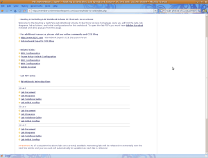
Access to the Volume IV workbook is the same as for all INE workbooks.  Once you’re logged in you’ll find (at present) three troubleshooting labs available.  The workbook will eventually contain 10 troubleshooting scenarios.  Each lab contains 10 trouble tickets which vary in value from 2 – 4 points.  You’ll also get the lab topology, along with initial configurations and the solution guide.

INE Workbook IV

INE Workbook IV

I rented some rack time at INE’s rack rental company, Graded Labs.  I booked a single, 5.5 hour session and planned to attempt the first two labs.  You’re allotted 2 hours for each lab, so I figured I should be able to complete both labs.  I was very wrong.

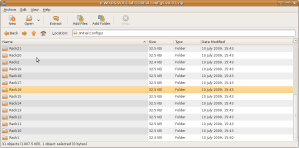
Graded Labs has a number of configurations for the INE product line which you can choose to have automatically loaded to your rack.  Unfortunately Graded Labs does not have the configs for the new Volume IV workbook yet.  This means that you will initially need to connect to each device and load in the appropriate config.  I had rented rack 16 and was worried that I would need to parse the initial configurations replacing IP addresses to fit the rack number, but INE has the initial configs for 31 different racks (1-30 and the mysterious rack 42) so you don’t need to go through the configs and change the IP addresses to match the rack.  It was just a matter of cutting and pasting in the appropriate configurations.

Initial Configurations For 31 Racks Included

Initial Configurations For 31 Racks Included

After loading the configurations, it was time to take a look at the lab.  I would very strongly recommend that you take the time to read the Workbook Introduction.  This six page PDF explains INE’s methodological approach to troubleshooting.  You will want to be familiar with it before attempting the labs as it will help you with troubleshooting as well as prepare you for the explanations in the solution guide.

After digesting the Workbook Introduction, it was time to look at the lab.  This is where the first surprises appear.

Lab Do’s and Don’ts:
•  Do not access the routers that are marked as restricted for your access.
•  Do not use the show running-config or show startup-config commands or their equivalents when performing troubleshooting.
•  Do not change or add any IP addresses from the initial configuration unless required for troubleshooting.
•  Do not change any interface encapsulations unless required for troubleshooting.
•  Do not change the console, AUX, and VTY passwords or access methods unless otherwise specified.
•  Do not use any static routes, default routes, default networks, or policy routing unless otherwise specified.
• Save your configurations often.

Those first two restrictions are killers.  While you will use the tried and true INE lab topology for these labs, each lab will include a number of restricted devices – outside of the normally restricted backbone devices.

The topology used for every scenario is the same that we use for all our RS products, including VOL1 (technology- focused labs), VOL2 (configuration mock lab scenarios) and VOL3 (core technologies scenarios).

However, unlike our previous workbooks, we restrict access to some of the devices in the lab topology. For every scenario this “restricted” set may be different and it is clearly outlined in the scenario’s baseline. Using this technique we increase the scenario complexity by allowing candidates to see only “one” side of the problem. When looking at the lab diagram, you will clearly see routers not under your control as being displayed in orange color. Also, when you log onto the “restricted” device, it will warn you using a banner message.

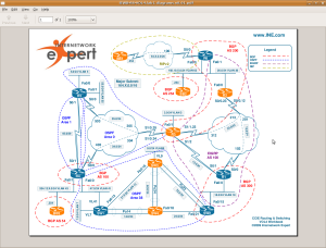
Lab 1 Topology - Note Restricted Devices in Orange

Lab 1 Topology - Note Restricted Devices in Orange

In lab 1 for instance, you are not allowed to access BB1, BB2, BB3, R2, R3, SW3, and SW4.  You’re pretty much on the honor system for the internal network devices as the you’ll be warned by a banner message, but only the first time you connnect (or if you telnet to the device(s)).

For instance, r3 is a restricted device:

Rack16R1#telnet 164.16.35.3
Trying 164.16.35.3 … Open

User Access Verification

Username: cisco
Password:

*****************************WARNING******************************
*                                                                *
*           Per the requirements of this scenario                *
*         You are not allowed to access this router              *
*                                                                *
*****************************WARNING******************************

Rack16R3>

You will not see the exec banner as long as the session to the console line is open from from the access server.  Regardless, it is important that you do not access the verboten devices during the lab.

While the restricted devices threw me an unexpected curve, it was the second requirement that really floored me.

In addition to the above restriction, we highly encourage you not using the show running-configuration, show startup-configuration commands or any other command that shows you the textual representation of the router’s configuration. This requirement makes you focus on using the show and debugging commands, which is invaluable when troubleshooting the real-world scenarios.

Our ultimate goal is not only prepare you for passing the Troubleshooting section of the CCIE R&S lab exam, but also to teach you a structured troubleshooting approach. As opposed to simple guessing and peeking at the routers running configurations you should learn using the debugging commands and interpreting various show commands output.

INE is serious about this too.  The solution guides will only use show and debugging commands to determine the root cause of each issue.  I don’t know if this will be a requirement in the actual lab; I certainly hope not!  In “real life” though, the use of debug commands is pretty much forbidden in the environments that I’ve worked in.  There’s a saying at my job “If you turn on a debugging command you had better have created a network change ticket, otherwise you’ve just created a job change ticket.”  Still, using the debug commands is a very good way to understand the underlying technology and there are some instances where you will get important troubleshooting information for a debug command that you cannot get in a show command.

For every ticket, we are going to follow the same structured procedure to resolve the issue.

Here is an outline of this procedure:

1. Build and Analyze the Baseline
2. Analyze the Symptoms (propose hypothesis)
3. Isolate the issue (gather more symptoms)
4. Fix the Issue (by comparing to the Baseline)

We recommend making your own diagrams, including the following
information:
• IP addressing + IGPs.
• Layer 2 topology.
• BGP diagram.
• IPv6 topology.
• Multicast and Redistribution diagram.

Overall, don’t spend too much time building the baseline – the goal is to spend around 20 minutes. By the end of the baseline analysis phase, you should have clear understanding of the protocols and applications deployed in your network.

This is a brief review of the systematic troubleshooting procedure that you’ll be using for the labs.  You’ll be familiar with the topology drawing bit from your practices labs.  Although, I did pick up some good tips from the solution guide about making topology maps.

Okay, enough jibba jabba about the labs.  Let’s actually dive into one.  That will be the focus of the next part of the review.

August 7, 2009

Internetwork Expert Volume IV (Troubleshooting) Workbook Review: Part 1

As we’re all painfully aware, the next version (4.0) of the CCIE lab exam goes live this October.  For those of us who did not nab a date before the cutover date, we’re looking at a different beast come October.  In addition to a number of new technologies (such as MPLS and Zone Based Firewall) and the dread Core Knowledge questions, there will be a brand new addition: troubleshooting.  Between the Core Knowledge section and the actual lab exam, there will be a troubleshooting section.  While details are still a little vague, here’s what Cisco has said about this section(may require CCO login):

Troubleshooting is allotted two of the eight hours required for the CCIE lab exam. Candidates will be presented with a series of trouble tickets for preconfigured networks and will need to diagnose and resolve the fault or faults. As with previous CCIE labs, the network will need to be up and running for the candidate to receive credit.  Candidates who finish the troubleshooting section early can move on to the configuration section, but they will not be allowed to go back to the troubleshooting section.

Here are some additional details culled from a recent Ask The Expert Section:

  • The Troubleshooting section will be independent from the Configuration section, i.e., it will be presented on a different scenario.
  • Once you finish the Troubleshooting you will move to the Configuration section that will be presented on a new scenario or topology.
  • The Troubleshooting section will have a maximum of 2 hours. The candidate will be presented a series of questions or ‘trouble tickets’ for a given scenario or topology. The referred topology will pre-configured.
  • Based on the information provided such as IP addressing diagrams, IGP routing diagrams, and so on you will work to identify and fix the issues. You will be given points for working scenarios.
  • The Troubleshooting section will have a certain number of trouble tickets and points allocated to the section. You will receive credits for the points you get. Your score on this section will show as, 30%, or 50%, or 80%, and so on.
  • You will need to get a minimum of 80% on each section of the exam to pass on the CCIE lab exam.
  • Yes, we are planning to post a sample Troubleshooting questions/trouble ticket for study reference.

Internetwork Expert has a poll up asking CCIE candidates which part of the new lab format scares them the most.  Troubleshooting is the number one choice.

I’ll admit that when I first heard about the addition of troubleshooting to the lab, I was unconcerned.  While I don’t spend any time(outside of practice labs) building complex OSPF networks, I do troubleshoot networks for probably a good 30% – 50% of each workday(not to mention after hours when on call).  Plus, I’ve always been pretty good at the initial troubleshooting sections in the vendor labs.

Petr Lapukhov from INE emailed me recently and gave me access to the first couple of labs in the new Internetwork Expert Volume IV workbook.  This is INE’s new product covering the troubleshooting section of the lab.  I agreed to try the first couple of labs and write my thoughts.  My first thought? I vastly underestimated how potentially difficult the new troubleshooting section could be!

While I have spent a considerable amount of time troubleshooting networks over the last ten (sigh) years, they’ve always been MY networks.  Well, at least they’ve always been networks with which I was very familiar.  So if a server goon bitches about not being able to ping his heart beat IP address, I can quickly re-educate (an exercise in futility) him about the fact that this network exists on a layer-2 only network that is not trunked nor associated with an SVI so he’ll only be able to ping other heart beat IPs sourced from the heart beat IP address on his box.  If I was not aware of the design of this network, then I would have to start with the usual battery of pings and traceroutes to (hopefully) get to the same conclusion.  In other words, familiarity with the network design will make troubleshooting much easier and quicker.  I also overlooked the fact that a good 90% of my daily troubleshooting is really mundane shit like checking speed/duplex, verifying MAC addresses, checking ARP tables, etc.  It’s thankfully very rare that I ever troubleshoot any complicated layer 3 issues.

So while I might feel (justified or not) that I have a lot of troubleshooting experience, a lot of that experience will be worthless in a lab scenerio…as I was soon to discover.  🙂

Core Knowledge Question of the Day: 07 August 2009

If a TCP connection does not complete the three-way handshake within a particular time period, TCP intercept sends a TCP reset to the server, cleaning up the connection.

Which TCP intercept mode does this statement best describe?

Highlight for answer: Watch mode.

August 6, 2009

Core Knowledge Question of the Day: 06 August 2009

By default, when does a Cisco router switch over from the root-path-tree to the source-specific SPT?

Highlight for answer: When the first packet is received from the shared tree.  You can change this with the ‘ip pim spt-threshold’ command.

August 4, 2009

Cisco Announces CCIE v4.0 Written Beta

Cisco has announced the beta exam for the new CCIE v4.0 exam.  For the reduced price of $50, this is a good opportunity for recertification for those with their digits or for those who may not have already taken the written exam and are studying for the new version of the lab.

Beta Available for CCIE Routing and Switching v4.0 Written Exam

The beta version of CCIE Routing and Switching Written Exam v4.0 (351-001) will be available for scheduling at all worldwide, Cisco-authorized Pearson VUE testing centers beginning August 11, 2009 and continuing through September 9, 2009. Candidates may schedule and take the exam on the same day. The beta exam will be offered at a discounted price of US$50, with full recertification or lab qualification credit granted to all passing candidates. Candidates preparing for this exam should refer to CCIE Routing and Switching 4.0 written exam topics for a detailed outline of topics covered. Registration on the Cisco Learning Network is required.

Click here for more information about CCIE written exam betas.

Reminders: Candidates will receive their results six to eight weeks after the close of the beta period. Therefore, CCIEs in suspended status with an expiration date before November 30, 2009 should recertify using another exam. Candidates may only attempt a beta exam once during the beta period.

August 3, 2009

Pardon The Cobwebs

Filed under: Cisco — cciepursuit @ 11:05 am

Sorry for the recent lack of posting.  I’ve been extremely busy lately with work and (mostly) family.  I’ll resume more regualr posting tomorrow.

July 15, 2009

Core Knowledge Question of the Day: 15 July 2009

A port in the Spanning Tree state of ‘blocking’ does not allow any type of traffic – true or false?

Highlight for answer: False – BPDUs are still allowed over the link.

July 14, 2009

Core Knowledge Question of the Day: 14 July 2009

Does an OSFP stub explicitly filter Type-4 LSAs, or is their absence in an OSPF stub area simply due to being unnecessary because the Type-5 LSAs have been filtered?

Highlight for answer: Actually, I don’t know the answer to this question.  I was thinking about it today.  In an OSFP stub area Type-5 LSAs are explicitly filtered.  There are no Type-4 LSAs present either.  I don’t know if they are explicitly filtered, or they are just never generated because the Type 5 LSA is filtered/never created?  It’s my understanding (possibly a misunderstanding) that the ASBR generates the Type-4 LSA, so…it must be explicity filtered at the ABR, right? <–This is WRONG! 🙂

—-

Thank you for the comments (big ups to Ivan P, Zeeshan, and Pavel Sefanov).  I think that I have this cleared up in my head now:

The ABR generates the Type-4 LSA. If the area is configured as a stub area, the ABR filters the Type-5 LSAs(generated by the ASBR) and does not generate a Type-4 LSA. So, technically, an OSPF stub configuration only explicitly filters Type-5 LSAs, but it implicitly filters Type-4 LSAs as well as there is no need for the ABR to generate a Type-4 LSA.

So if you were to tell a co-worker that both Type-5 and Type-4 LSAs are filtered, you would be technically wrong.  😦

Ivan Pepelnjak from Cisco IOS Hints and Tricks wrapped it up nicely:

To make it more explicit: the type-4 LSA is the glue that ties together a type-5 LSA originated by an out-of-area ASBR with the ABR flooding type-5 into the area. If there are no type-5 LSAs, type-4 LSAs are not needed (you will also not see them for ASBRs in the same area).

July 13, 2009

Core Knowledge Question of the Day: 13 July 2009

What are the two tables that CEF utilizes to switch packets?

Highlight for answer: Forwarding Information Base(FIB) and [CEF] adjacency table.

Next Page »

Blog at WordPress.com.